Proceedings of the 2003 International Symposium on Liquid Metal Procesing and Casting Nancy, France Semptember 21—24, 2003
Electroslag Refining of Titanium For the
Removal of Nitrogen-Rich Inclusions
A.D. Ryabtseva, A.A. Troyanskya, V.V. Pashynskya, M.V. Samborskya
William T. Carter, Jr.b, Mark G. Benz b
a Donetsk National Technical University, Ukraine b GE Global Research Center, Niskayuna, New York 12301
Abstract. Nitrogen-rich inclusions are
detrimental to the physical properties of titanium alloys. They have, as a
rule, a core of TiNx, surrounded by layers of a-Ti and b-Ti, containing nitrogen. Nitrogen-rich
inclusions, also known as «hard alpha» inclusions, are very brittle in nature
and may crack during service, serving as initiation sites for low-cycle
fatigue. A large nucleation site results in a large initial crack, resulting in
fast fatigue crack growth and short service life. It is not the general content
of nitrogen in the alloy system that limits fatigue life; instead, the
life-limiting factor is the presence of discrete brittle nitrogen-rich inclusions.
Nitrogen-rich
inclusions form during titanium sponge manufacturing. The current titanium
industry relies on fragmenting the titanium sponge into small pieces and using
various melting methods (vacuum-arc,electron-beam and plasma arc) that allow
the inclusions to dissolve into the liquid titanium alloy. The titanium
industry has aggressively implemented melting and control strategies over the
past 15 years and has greatly improved processing using hearth melting.
Investigation of the rate of dissolution of nitrogen-rich inclusions submerged in liquid titanium shows that this process is relatively slow, at approximately
2.2 micron/s. Thus, hearth remelting processes must be run slowly to allow time
for dissolution. This paper offers a fast alternative processing method using
electroslag refining.
Analysis of
the Ti-N phase diagram shows that all nitrogen-rich inclusions melt at a higher temperature than titanium itself. The density if titanium nitride (TiN) is 5.43 g/cm3, which is higher than density of titanium (4.5 g/cm3). Consequently, removal of nitrogen-rich inclusions during electroslag refining as a result of
melting or floating is not likely. However, thermodynamically favorable
conditions for the removal of nitrogen-rich inclusions may exist in electroslag refining under calcium-containing fluxes, which provide an extremely low
partial pressure of nitrogen in the slag. In this paper the results of
experiments for the removal of nitrogen-rich inclusions during electroslag
refining of commercial titanium alloy Ti-6-4 are described. Electroslag
refining of ingots heavily seeded with nitrogen-rich inclusions is shown to
successfully remove inclusions at a high rate.
1. INTRODUCTION
It is known that the quality and service characteristics of parts made from titanium
and alloys depend on their chemical composition, the purity of the material,
and the presence of nonmetallic inclusions. So-callednitrogen-rich inclusions
(NRI) are detrimental to the physical properties of this material.
Nitrogen-rich inclusions have, as a rule, a core of TiNx, surrounded by layers of a-Ti and b-Ti, containing nitrogen. Nitrogen-rich
inclusions, also known in literature as «hard alpha» inclusions, are very
brittle in nature and may be responsible for cracks nucleation in metal. In
this case the problem is not the general content of nitrogen in system, but the
concentration of nitrogen into local inclusions that are inclined to activate
cracks. Hard or brittle inclusions, pores or their combinations are often the
sites for fatigue crack nucleation. Large nucleation sites, result in bigger
initial cracks, resulting in higher velocity fatigue crack growth and shorter
life [1,2].
Elimination
of NRI or minimization of their size has become a significant problem in the
titanium industry. NRI generally form during the step of titanium sponge manufacturing,
and must be removed during subsequent sponge sorting or ingot melting
operations [3,4]. Fragmentation of titanium sponge to the pieces of small
size [5] and using of melting methods that increase the time of treatment in liquid state (triple vacuum-arc,electron-beam and plasma remelting) improve the situation, but can not
guarantee the complete removal of inclusions. Ultrasonic inspection is used as
a final step to identify and reject metal that contains NRI’s.
Analysis
of the Ti-N equilibrium phase diagram shows that all nitrogen rich inclusions
melt at higher temperatures than titanium itself [6]. The density if titanium
nitride (TiN) is 5.43 g/cm3, which is higher than the density of titanium (4.5 g/cm3) and its alloys. Consequently, the removal of NRI by electroslag
remelting by melting or floating is not likely. The rate of dissolution of NRI
submerged in liquid titanium has been shown to be slow (approx. 2.2 micron/s)
[8]. Thus, decreasing the size of NRI by dissolution during ESR is restricted.
However, thermodynamically favorable conditions for the removal of inclusions
of this type may exist in electroslag remelting under calcium containing fluxes
[9]. This process provides low (near 10-11 kPa) partial pressure of
nitrogen in the slag, and results in the possibility of removing NRI from
titanium and its alloys [10,11].
In this
work the results of experiments for removing nitrogen rich inclusions from
titanium alloy Ti-6-4 during ESR are described. Ti-6-4 is a widespread
construction material in the aviation, chemical and power industries. It is
usually produced from titanium sponge followed by hearth melting and vacuum-arc
remelting. Parts are subjected to total ultrasonic inspection. If defects in
the form of NRI are found, the product is rejected at considerable economic
loss.
2. EXPERIMENTAL PROCEDURE.
Considerable
care was taken in the preparation of seeded consumable electrodes to ensure
that the artificially introduced NRI would not fall out of the electrode during
remelting. Two types of NRI were investigated: nitrided titanium sponge with
30% (at.) nitrogen content; and titanium nitride TiN powder with content of 49%
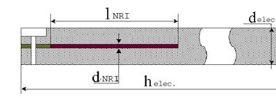
(at.) nitrogen. The diameters of inclusions were 3-mm and 1-mm. The inclusions
were pressed into a titanium alloy pipe that was evacuated and electron beam
welded to close the pipe ends prior to hot isostatic pressing at 1475 K and
pressure 2•105 for 4 hours. This formed an inclusion capsule that was easily inserted into
electrodes. Electrodes were drilled along the longitudinal axis and the HIPed
inclusions capsules were introduced into holes. The openings were closed with
titanium alloy plugs that were welded using argon-arc welding. The assembled
electrodes were hot isostatically pressed (Fig. 2). In this manner, consumable
electrodes (75-mm dia.) from commercial titanium alloy Ti-6-4 were seeded with
artificially manufactured NRI in the upper part of electrodes as shown in
Figure 1.
Electroslag
remelting was carried out in an electroslag remelting furnace that incorporates
a melting chamber for environmental isolation. Experiments were performed on an
A-550 unit [12], with a copper water-cooled crucible 135-mm in diameter and
500-mm in length. The water-cooled chamber was mounted directly on top of the
crucible. The system was designed with appropriate seals to permit vacuum or
over-pressure above the melt. The chamber was evacuated before melting and
back-filled with argon. During the process, an argon pressure of 15-kPa was
maintained to compensate for leakage through various seals.
Pure
calcium fluoride powder plus metallic calcium was used for the flux. The flux
was melted directly in the crucible using a cold start procedure. During the
melting of the CaF2—Ca mixture, calcium vapors decrease the
partial pressure of nitrogen and oxygen to value of 10-13-kPa in the
chamber.
Experimental
melting was conducted with electric parameters (47-V, 3.0-kA) that are known to provide a
high-quality of surface on ingots of this size. The composition of flux (CaF2 or CaF2 + Ca) and the
length of the melted part of electrode with embedded artificial NRI were varied
in an experimental program.
Figure 1. Schematic of electrode with
centerline inclusion.
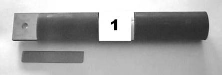
Figure 2. General view of electrode
from titanium alloy Ti-6-4 with centerline inclusion.
Melt #1
was taken as a standard; it was carried out under pure calcium fluoride flux
(2300-g CaF2). The length of the melted part of the electrode with a
1-mm centerline NRI made from TiN powder was 125-mm. Melts 2 and 3 differ from
the standard by the addition of 100-g of metallic Ca to the flux and the length
of the melted part of electrodes with NRI was 35 and 85-mm, respectively.
The cast
experimental ingots were ultrasonically inspected with a Krautkramer Branson
USN 52 device at a frequency of 2.5 MHz, followed by step-by-step cutting on a
lathe with visual inspection. The gas content was determined on samples taken
from upper ingots (200-mm in height) using a LECO analyzer.
3. RESULTS
3.1 Investigation of the Ingots
Upon
opening of the chamber after melts 2 and 3, a calcium deposit on all surfaces
of the crucible burns. This is the result of excessive concentration of calcium
vapors in melting zone and is an indirect confirmation of the fact that the
addition of metallic calcium to the CaF2 flux forms a deeply deoxidized media.
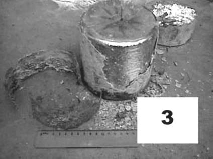
Visual inspection of the surface of the ingots shows that the addition of
metallic calcium to the CaF2 flux sharply decreases the residual content of oxygen and nitrogen in
the zone of melting. This is indicated by a clear silver color (Fig. 3) on the
surface of ingots 2 and 3 (without oxidation) in comparison with dark gold
color of ingot 1.
Figure 3. ESR ingot from titanium alloy
Ti-6-4 (melt 3).
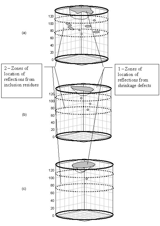
Ultrasonic
inspection of the experimental metal establishes the existence of two zones of
reflections localization in all ingots (Fig. 4). The first zone is located in
the upper part of the ingot and is characterized by multiple reflections,
located in central axial areas. The height of zones in the longitudinal
direction was not more than 20 to 30-mm from the top of ingot. From the
amplitude of reflections and their location, these were determined to be
reflections from shrinkage defects. The second zone of reflection localization
is located at a distance 35 to 65-mm from the top of ingot. These reflections
were different for each of the variants of melting conditions. The maximum
number of signals was in Ingot #1, while Ingot #2 had practically no
reflections in this zone. The number and amplitude of reflections in Ingot #3
was lower then in Ingot #1.
To
confirm the results of ultrasound inspection, the ingots were machined in a
layer-by-layer manner, starting at the top of the ingot. It was established
that the ultrasonic signals in the upper part of ingots (Fig. 4) corresponded
to shrinkage porosity with a clear, un-oxidized inner surface (Fig. 5). In the second zone of
reflections for ingot 1, several residues of the partially destroyed nitrogen
rich inclusion were found (Fig. 6). In ingots 2 and 3 these reflections
correspond to zones of high-nitrogen solid solution (Fig. 7), not nitrogen-rich inclusions.
Figure 4. Schematic of location of ultrasonic
waves reflections. a) Melt 1. b) Melt 2. c) Melt 3.
Figure 5. Typical Shrinkage Porosity.
Figure 6. Residues of undestroyed NRI in Ingot #1.
Figure 7. Nitrided zones in Ingot #3.
The gas
content of the metal and the concentration of dissolved nitrogen in the Ti-6-4
alloy ingots was determined in order to investigate the possible process of
decomposition of nitrogen-rich inclusions (NRI) during remelting under
different slags. As shown in the table, the nitrogen content in the metal of
Ingot #1 did not increase significantly, whereas ingots 2 and 3 do show an
increase. The addition of metallic calcium into the ESR chamber is associated
with an increase in the nitrogen content in metal. The higher the mass of the
introduced NRI, (melts 2 and 3) the higher the concentration of nitrogen in the
metal. This is evidence of the fact that during ESR melting under
calcium-containing slag, thermodynamic conditions for decomposition of NRI and transfer of the nitrogen into the metal are provided. The oxygen content stayed
essentially unchanged in all investigated variants of remelting.
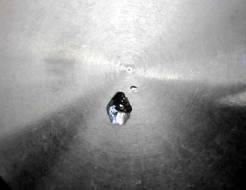
For Ingot #1, the melt rate was much higher than the rate of decomposition of the NRI rod. It eventually reached the surface of the slag-metal boundary, formed a
short circuit, and was destroyed. Deposits of the rod then fell into molten metal
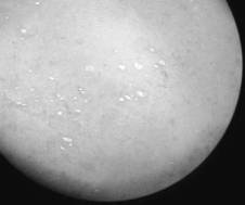
bath (Fig. 8). The character of Ingots #2 and #3 were different (Fig. 9); the
rate of decomposition of the NRI and the rate of electrode melting were
comparable in these cases.
Table I. Nitrogen and oxygen content in Ti-6-4 alloy.
Ingot
Number
Oxygen Content
(wt %)
Nitrogen
Content (wt%)
Initial
0.17 – 0.18
0.010 – 0.020
1
0.17 – 0.22
0.020 – 0.029
2
0.21 – 0.22
0.026 – 0.030
3
0.18 – 0.19
0.033 – 0.041
Figure 8. Electrode face after melting, with
prominent NRI in Electrode #1.
Figure 9. Top of Electrode #2.
3.2 Investigation of the Partially Melted Electrodes
Additional
confirmation of the beneficial thermodynamic conditions for the decomposition
of NRI under calcium-containing slag can be obtained through examination of the
electrodes tips with embedded centerline inclusions, after partial melting. To
obtain samples for this investigation, the ESR process was interrupted when
part of consumable electrode with the inclusion was in the process of melting.
For the purposes of metallographic analysis and the measurement of
microhardness, the tip of the electrode was cut off and a metallographic
section (fig. 10) was made by machining, grinding and polishing. The section
passes longitudinally through the axis of the inclusion.
Examination
of the structure of the frozen droplet of metal around the inclusion shows that
the inclusion residue extends past the surface of electrode and is surrounded
by crystallized metal in such a manner that the lateral surface of the
inclusion is in contact with molten metal of the droplet and tip of inclusion
contacts the molten slag pool; this was true in all samples. However, the
internal structure of the frozen droplet is different for different inclusion
types or diameters.
Recall
that the inclusions were introduced into the electrodes via a titanium
inclusion capsule. During the melting of the electrode, the titanium capsule
was exposed and melted and the NRI comes into direct contact with the molten
slag and the liquid metal layer that coats the electrode surface. A noticeable
diffusion interaction takes place between the inclusion and the liquid layer
that surrounds the inclusion.
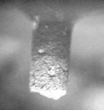
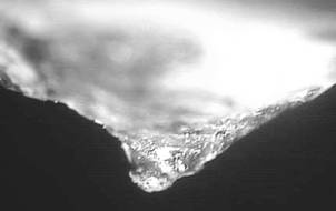
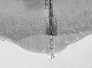
Figure 10. The general view of NRI from TiN
powder 1-mm in diameter longitudinal section with solidified droplet after
remelting interruption.
For the
NRI made from nitrided titanium sponge, there is metallurgical evidence of
early melting of the inclusion (Fig. 11a). Areas with a modified structure,
probably a-solid
solution, appear inside the inclusion (Fig. 11b) as evidence of diffusion
processes in the NRI material. As a result there is a change in the chemical
composition of the droplet compared with the composition of the electrode. At
the same time, from the electrode areas that are far from inclusion, molten
metal with a lower concentration of nitrogen enters into the droplet. In Fig. 11c the formation of dendrite structure on the boundary between a droplet and
the surface of melting electrode is shown. The figure illustrates the
difference in chemical composition of the mixing molten materials. Therefore
the assumption may be made that diffusion redistribution of nitrogen causes a
decrease in its concentration in the inclusion and, consequently causes a decrease
in the melting temperature of NRI that was prepared from titanium sponge.
Obviously
that rate of diffusion processes is not enough to provide effective dissolution
of the inclusion. In particular, the diameter of the exposed inclusion is
practically constant, and equal to its initial diameter. This is evidence of
ineffective dissolution of NRI. At the same time, the part of NRI that is in
contact with molten slag has a rounded shape and is relatively small compared
to the total length of the prominent part of inclusion.
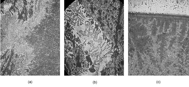
Figure 11. Structures of transition zones,
formed during the remelting of electrode with NRI from nitridized titanium
sponge. a — structure of boundary «metal of droplet — lateral surface of NRI», x100; b — nonuniformity of structure in inclusion, x100; c — formation of dendrites on the boundary «droplet — surface of melting electrode», 50x.
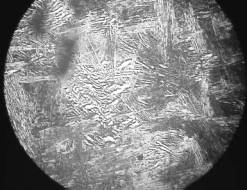
These peculiarities become even more
apparent during examination of electrodes residues with NRI from TiN
powder. An investigation of the
boundary between the droplet metal and the NRI lateral surface shows (Fig. 12a), that between the lateral surface of NRI and molten metal, a diffusion
zone 10-30 microns in width was formed. But there are no considerable
structural changes in the inclusion. As shown in Fig. 12b, the dendrite structure of contact zone of droplet and electrode surface does not form in this case. The high melting temperature of the NRI and its chemical stability result in the formation
of a steady chemical TiN compound; the dissolution of inclusions of such size
by the diffusion of nitrogen into the molten metal droplet is impossible.
There is
no considerable change in the structure associated with decreasing the
inclusion diameter. Diffusion interaction with droplet metal is weakly
developed. At the same time, a view of the inclusion residue that is in contact
with molten slag does show evidence of the development of a dissolution
process. With decreasing inclusion diameter, the length of inclusion in contact
with slag decreases. At optimal remelting parameters the inclusion practically
does extend past the metal droplet.
It is
known /13,14/, that hardness of titanium and its alloys depends on content of
impurities, primarily oxygen and nitrogen. Therefore to obtain detailed
evaluation of nitrogen distribution, microhardness measurement were performed.
Measurements were performed along straight lines, parallel to longitudinal axis
of inclusion, from the electrode surface to the tip of droplet at a distance
0.5 and 2-mm from the lateral surface of NRI. The results of measurement for
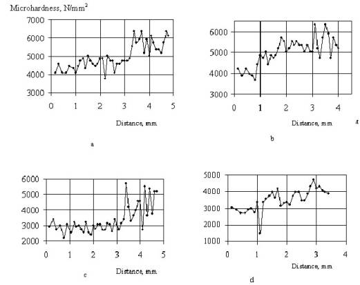
samples with NRI 3-mm in diameter are shown on Fig. 13.
These
measurements indicate that the values of hardness in samples with the NRI
(which have increased concentration of nitrogen) are higher than in the case of
NRI from titanium sponge. The maximal level of hardness is in the regions where
the droplets were in contact with the molten slag pool.
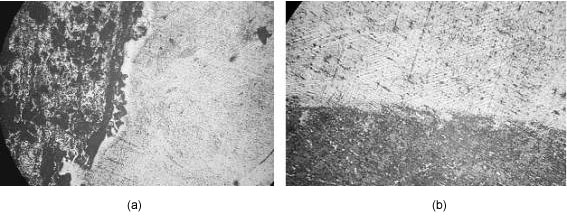
Figure 12. The structures of transition zones
formed during remelting of electrode with NRI from TiN powder, x50. a)
Structure of boundary between metal droplet and NRI lateral surface. b)
Structure of boundary between droplet and surface of melting electrode.
Figure 13. Distribution of microhardness in
crystallized droplet.
a — sample with NRI from TiN powder, 0.5 mm from inclusion;
b — sample with NRI from TiN powder, 2.0 mm from inclusion;
c — sample with NRI from titanium sponge, 0.5 mm from inclusion;
d — sample with NRI from titanium sponge, 2.0 mm from inclusion
4. CONCLUSIONS
The
investigation shows that the use of calcium-containing fluxes in a chamber ESR
is an effective means of removing nitrogen-rich inclusions from titanium
alloys. During electroslag remelting, nitrogen-rich inclusions are destroyed as a result of interaction between the inclusions and the slag. An investigation
of the electrodes shows that the inclusions do not react significantly with the
liquid titanium droplets directly; instead, dissolution occurs when the
inclusion comes into contact with the slag. The nitrogen is not removed from
the system, but is dissolved into the titanium metal. This process may be
suitable alternative to hearth melting.
5. REFERENCES
E.M.
Grala: «Characterization of Alpha Segregation Defects in Ti-6Al-4V Alloy,» AFML Technical Report AFML-TR-68-304,
1968.
J.L.
Henry, S.D. Hill, J.L. Schaller, and T.T. Campbell: «Nitride Inclusions in
Titanium Ingots: A Study of Possible Sources in Production of Magnesium-Reduced
Sponge,» Met. Trans., 4, 1973,
1859-1864.
J.L.
Henry, S.D. Hill, W.E. Anable, and J.L. Schaller: «Source and Control of
Nitride Inclusions in Titanium, Bureau of Mines,» US Department of the Interior
1974, Bu Mines RI 7933, Washington, DC.
S.R.
Seagle and R.L. Fisher: «Critical Review: Raw Materials», Sixth World Conference on Titanium, Cedex, France, P. Lacombe, R.
Tricot, and G. Beranger, Eds., 1988, 565-572
P.J.
Bania: «Production of Titanium Articles That Are Free From Low Density Inclusions,»
US Patent 4,678,506, July 7, 1987.
N.P.
Lyakishev. – M: Machinebuilding, Eds. State Diagrams of Dual Systems:
Guide-book in 3 Volumes.: V. 3.
part 1, 1999, 880.
Rabinovich
V.V., Khavin Z.Ya., Short Chemical Guide-book Edition 2, 1978, 308.
B.P.
Bewlay and M.F.X. Gigliotti: «Dissolution Rate Measurements of TiN in Ti-6242,»
Acta. Met., 45 (1), 1997, 357-370.
M.G.
Benz, P.J. Meschter, J.P. Nic, L.C. Perocchi, M.F.X Gigliotti, R.S. Gilmore,
V.N. Radchenko, A.D.Riabtsev,O.V.
Tarlov, V.V. Pashinsky «ESR as a
Fast Technique to Dissolve Nitrogen-Rich Inclusions in Titanium,» Materials Research Innovations 6 1999,
364-368.
A.
Troyansky, et. al., «Investigation of mechanism of destroying of nitride
inclusions in titanium ingots at electroslag remelting under active
calcium-containing fluxes.» Theory and
Practice of Metallurgy, 6 (20), 2000, 11-12.
Ryabtsev
A.D., et. al., «Using of Electroslag Technology for Refining of Titanium and
Alloys on its Base from Nitrogen-Rich Inclusions,» Problems of Special Electrometallurgy, 3, 2002, 10-13.
A.D.
Ryabtsev. «Unit for electroslag remelting of metals and alloys with high
reaction ability under active metal-containing fluxes in controlled atmosphere
or vacuum» Transactions of DonSTU.
Metallurgy.14, 1999, 58-60.
V.A. Liskovich,
et. al., «About the influence of impurities on hardness of titanium» Proceedings of High Educational Schools.
Nonferrous Metallurgy, 5, 1980, 23-26.
S.M.
Gurevich. – М.: Naukova Dumka, Eds., Metallurgy and Technology of Welding of
Titanium and its Alloys, 1979, 300.